

Cold-formed steel (CFS) is sheet steel shaped into structural profiles by bending or rolling at room temperature. This manufacturing process produces thin-walled components with controlled dimensions. It is widely used in modern residential and commercial building construction.
Cold-formed steel framing uses studs, tracks, joists, and rafters to form wall, floor, and roof assemblies. Panelization allows selected frames to be assembled in factory conditions before they reach the site. For engineers, performance depends on managing axial load, lateral load, and local buckling through profile design and connections. Thermal bridging also requires attention when specifying insulation and detailing the building envelope.
What Is Cold Formed Steel?
Cold-formed steel (CFS) is distinguished not only by its forming method but also by the engineering of its thin-walled cross-sections. Manufacturers process Coil Steel into profiles whose dimensions and geometry are specified for particular structural or nonstructural functions. Unlike conventional hot-rolled members, these components are designed around efficient material distribution.
Several characteristics determine how those profiles perform in practice:
- Profile geometry: A C-Section combines a Web, Flange, and Lip/Stiffener to improve stiffness while limiting unnecessary material use.
- Material specification: Yield Strength and sheet thickness influence the loads a member can resist and the applications it can serve.
- Corrosion protection: Galvanization provides a protective zinc coating, although coating requirements depend on the intended exposure conditions.
- Manufacturing detail: Automated equipment can produce consistent profile dimensions and incorporate a Service Hole (Punchout) where specified by the design.
Compared with hot-rolled steel, CFS is particularly suited to repeatable, lightweight framing components rather than heavy primary structural members. However, selecting a profile involves more than comparing weight or thickness. Engineers must verify its geometry, connections, restraint conditions, and compliance with applicable design standards before determining whether it meets a project’s structural requirements.
Cold Formed Steel Framing Systems
Cold formed steel framing systems combine wall, floor, and roof assemblies into a coordinated structural arrangement. In multi-storey construction, accurate profiles alone cannot prevent installation conflicts if openings, floor levels, and connection details are developed independently. System planning must establish how loads move through the building and how each assembly interfaces with adjacent structural elements.
Key design considerations differ across the main assemblies:
- Load-bearing walls: Align supports between storeys and position Shear Wall elements to resist horizontal forces.
- Floor systems: Coordinate Joists, bearing points, and Diaphragm Action to transfer forces toward the intended structural elements.
- Roof systems: Establish span arrangements, connection geometry, and resistance to wind uplift before manufacturing roof frames.
- Non-load-bearing partitions: Accommodate structural Deflection through suitable movement details, including Track-in-Track connections where specified.
Construction strategy also influences these decisions. Compared with site-built framing, Panelization transfers assembly and dimensional checks to factory conditions, making transport limitations and installation order important considerations. Site-built methods offer greater flexibility when late architectural changes occur but require additional on-site coordination. BIM (Building Information Modeling) helps maintain consistency between structural specifications, production information, and installation documentation throughout the project.
Sections and Profiles
Selecting the appropriate profile requires evaluating its structural function, rather than focusing exclusively on steel thickness. A wall Stud has different requirements from a Joist supporting a floor assembly. Profile selection influences structural performance, fabrication efficiency, material consumption, and assembly accuracy.
Different cross-sectional configurations serve specific construction requirements:
- C-Section profiles are commonly selected for repetitive framing members when their geometry and restraint conditions meet structural requirements.
- U-Section profiles used as Tracks (or Channels) must accommodate the specified Stud dimensions and connection details.
- A Back-to-Back Stud configuration can accommodate increased loads when its connections are designed to enable the individual members to work together.
- Box Section Columns may be considered for concentrated loads, although fabrication requirements and connection accessibility need particular attention.
Profiles manufactured from similar quantities of steel can perform differently because cross-sectional geometry influences stiffness and susceptibility to Local Buckling or Distortional Buckling. Engineers therefore examine Moment of Inertia (I), Slenderness Ratio, and connection requirements before approving a Built-up Section. Selecting profiles according to these characteristics helps avoid unnecessary material consumption and potential manufacturing complications.
Studs and Other Framing Components
Openings introduce concentrated forces into a wall, so the arrangement of Studs around doors and windows deserves particular attention. A King Stud runs the full wall height beside an opening, while a Jack Stud supports the Header (Lintel). Where additional reinforcement is required, a Jamb Stud strengthens the opening’s sides. Cripples complete shorter framing zones above headers or below window sills.
Beyond openings, Noggin (or Bridging) members restrain Studs against twisting and help maintain alignment. Self-Drilling Screws connect these components according to specified fastening patterns. During detailing, engineers must coordinate screw placement, member continuity, and the transfer of concentrated loads before fabrication begins.
Framing Details and Connections
A reliable framing design depends on how individual members transfer forces through their connections. Poorly detailed joints can compromise structural performance even when the profiles themselves meet engineering requirements. Connection design must account for applied loads, material thickness, fastener capacity, and the geometry of adjoining components.
The following details require particular attention during engineering and fabrication:
Connection type | Key detailing requirements |
Steel-to-steel connections | Specify Self-Drilling Screws according to material thickness, connection loads, fastener spacing, and minimum edge distances. |
Multi-member connections | Position each Gusset Plate to accommodate the specified forces, considering plate thickness and fastening arrangements. |
Wall-to-foundation connections | Coordinate Hold-down locations, anchor embedment, and concrete capacity to resist uplift and overturning forces. |
Connection drawings should distinguish factory-installed fasteners from those requiring installation on-site. This distinction becomes particularly important when assembled frames limit access to certain connection points.
Inspection requirements also deserve attention before production begins. Steel thickness, fastener installation, and anchor positioning must correspond to the approved engineering details. Depending on the project location, applicable requirements may include AISI S100 or EN 1993 (Eurocode 3). Accurate documentation helps fabrication and construction teams maintain the intended connection performance without unnecessary modifications during installation.
Design Considerations
A residential project near a busy road presents challenges beyond structural strength. Occupants expect stable floors, effective sound insulation, and comfortable indoor conditions throughout the year. Meeting these expectations requires engineers to consider structural performance alongside building physics and architectural requirements from the earliest design stages.
Several factors influence the performance of the completed building:
- Floor comfort: Engineers should assess Deflection under expected occupancy loads and evaluate vibration, particularly where longer floor spans are specified.
- Acoustic performance: STC (Sound Transmission Class) ratings help compare tested wall assemblies. Actual performance also depends on insulation, lining materials, and installation quality.
- Moisture management: Air leakage and vapor movement require careful assessment to prevent Interstitial Condensation within external wall assemblies.
- Fire safety: Specifying tested fire-resistant assemblies is essential. Noncombustible steel alone does not establish the fire resistance of an entire wall or floor system.
These requirements should be evaluated together rather than addressed through separate design decisions. For example, changing an internal lining to improve acoustic performance may also affect the assembly’s fire resistance. Reviewing the complete assembly before construction helps engineers identify potential conflicts and select materials that satisfy multiple performance requirements.
Wall and Roof Framing
A building with multiple roof slopes requires careful coordination between supporting walls and roof geometry. Variations in wall height, ridge position, or roof pitch can affect structural alignment and complicate assembly. Planning these relationships before manufacturing helps ensure that individual components fit the intended architectural layout.
Several practical considerations influence wall and roof construction:
- Supporting wall elevations must correspond to the architectural roof layout, particularly where different building sections meet.
- Rafters and roof trusses require clearly defined bearing positions, especially around hips, valleys, and changes in roof direction.
- Openings for skylights and ventilation equipment should be incorporated into framing drawings before manufacturing begins.
- Roof overhangs must accommodate the intended cladding, drainage arrangements, and architectural dimensions.
Roof complexity also influences the construction sequence. Compared with a conventional gable roof, an irregular design may require more individually detailed components and additional coordination during installation.
Temporary stability must be maintained throughout erection until the permanent structural system is completed. Before installing roof components, construction teams should verify wall positioning and elevations against approved drawings. These checks help minimize adjustments during assembly and maintain dimensional accuracy across the completed structure.
Wall Framing
Wall framing begins with converting architectural drawings into a precise layout for each wall assembly. Designers distinguish between load-bearing and non-load-bearing walls, considering building dimensions, panel sizes, and site accessibility. Larger wall sections may require subdivision to accommodate transportation and lifting equipment. Careful coordination of corners, junctions, and service routes helps prevent conflicts during construction.
During production planning, several checks improve manufacturing accuracy. These include verifying panel dimensions, confirming component identification, and establishing an appropriate installation sequence. Panelization Software supports the preparation of production data from approved designs. Clearly documented layouts also help construction teams position individual panels correctly and reduce unnecessary adjustments on-site.
Roof Framing
Roof framing must accommodate the loads imposed by roofing materials, weather conditions, and maintenance activities. In regions with heavy snowfall, engineers assess snow accumulation and uneven loading when determining structural requirements. Flat roofs require additional consideration of rainwater accumulation and drainage performance.
For trussed roofs, the arrangement of internal members influences how forces travel between the upper and lower chords. Permanent Strapping and other specified bracing measures help restrain members against lateral movement. Roof sheathing may also contribute to Diaphragm Action when appropriately designed and fastened. These considerations determine member specifications, bracing arrangements, and the structural performance of the completed roof.
Roof Framing Details
Precise detailing is essential where roof components meet structural supports and architectural finishes. At the roof-to-wall junction, heel height must provide sufficient space for the specified insulation without obstructing ventilation paths.
Apex and splice connections require accurate positioning, while eaves must accommodate fascia installation and gutter arrangements. For prefabricated roof assemblies, dimensional tolerances and connection accessibility should be verified before production. Coordinating these details helps prevent installation conflicts and ensures compatibility between structural framing and roofing materials.
Applications in Construction
Construction projects have different requirements depending on their scale, location, and intended use. Cold-Formed Steel (CFS) accommodates various building types, from small residential developments to large industrial facilities. Its application depends on structural requirements, architectural complexity, and the construction method selected for each project.
The following table highlights how application requirements differ across construction sectors:
Application | Construction requirements |
Commercial buildings | Adaptable interior layouts and coordination with building services |
Modular construction | Standardized component dimensions and transportation compatibility |
Industrial facilities | Integration with primary structures and accommodation of operational requirements |
Building extensions | Assessment of existing structural capacity and additional building loads |
Unlike conventional construction methods that rely heavily on sequential on-site activities, prefabricated steel systems allow certain building components to be prepared in advance.
However, application suitability depends on more than manufacturing efficiency. Commercial developments may prioritize interior flexibility, while industrial facilities often require uninterrupted operational space.
Project teams must evaluate installation accessibility, transportation restrictions, and regulatory requirements before selecting their construction strategy. These considerations help determine whether a complete steel framing system or a combination of construction materials is appropriate.
Structural Applications
Structural applications require an understanding of how different building materials interact within a shared supporting framework. In hybrid construction, Cold-Formed Steel (CFS) members can be combined with conventional steel or concrete elements to accommodate project-specific requirements.
Engineers must evaluate the structural compatibility of these materials, particularly where different stiffness characteristics influence the distribution of forces.
For projects involving additional storeys, the capacity of the existing structure and foundation must be verified before introducing new framing elements. Building geometry, differential movement, and construction tolerances also influence the feasibility of combining structural systems. These assessments establish whether the proposed arrangement satisfies the required engineering criteria.
Residential Buildings
Housing developments require construction methods that accommodate different architectural layouts without unnecessarily increasing production complexity. Cold-Formed Steel (CFS) is suitable for single-storey and multi-storey residential projects, including detached houses, terraced housing, and apartment buildings.
For developers managing multiple properties, standardized layouts can simplify material planning and construction scheduling. Individual residential projects, however, may require customized arrangements for balconies, staircases, and additional living spaces.
Residential planning must also consider how kitchens, bathrooms, and future modifications affect the building layout. Coordinating these requirements during the design stage reduces the likelihood of alterations after manufacturing and helps accommodate different housing configurations.
Framing Machines
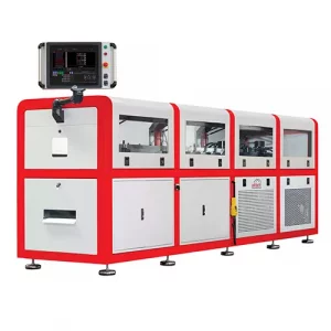
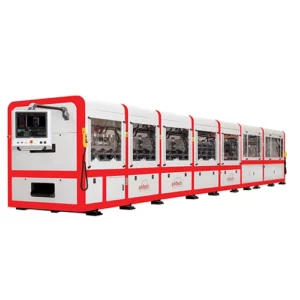
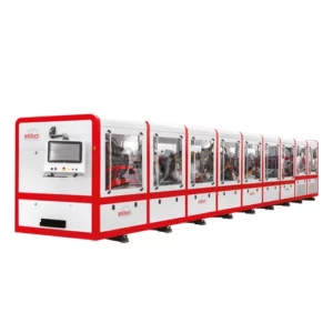
Manufacturing capacity depends on more than production speed. For a factory handling different construction projects, equipment must accommodate specific material thicknesses, profile dimensions, and manufacturing requirements. Modern framing machines transform Coil Steel into accurately manufactured components through automated forming, punching, and cutting operations.
Choosing suitable equipment requires evaluating several production factors:
- Single-profile machines are suitable for manufacturing operations with relatively consistent profile requirements, particularly where frequent configuration changes are unnecessary.
- Multi-profile machines provide greater flexibility when production schedules involve different profile dimensions and construction specifications.
- Integrated tooling stations perform cutting, notching, and punching operations, including the preparation of connection points and Service Hole (Punchout) locations.
- Software-controlled adjustments can reduce manual intervention when switching between supported profile dimensions.
Equipment selection should also account for production volume, operational costs, and factory infrastructure. A machine capable of processing thicker steel is not necessarily the most economical choice for manufacturing lightweight residential components.
Before investing, manufacturers should examine achievable dimensional tolerances, maintenance requirements, and material handling arrangements. Comparing these factors against actual production demands helps determine which equipment configuration offers the appropriate balance of flexibility, manufacturing capacity, and operational efficiency.
Design and Manufacturing Software
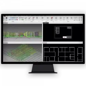
A late architectural revision can affect numerous framing components, particularly when manufacturing has already been scheduled. Integrated design and manufacturing software helps coordinate these changes by connecting detailed building models with production instructions. This digital workflow reduces the need for manual data transfer between engineering and fabrication teams.
An effective software workflow involves several stages:
Stage | Main function |
Design preparation | Import CAD drawings and develop detailed framing models. |
Design verification | Check profile dimensions, connections, and potential frame collisions. |
Production planning | Generate manufacturing files, material reports, and assembly documentation. |
Manufacturing execution | Transfer production instructions to compatible equipment and record manufacturing operations. |
Compatibility with BIM (Building Information Modeling) platforms is particularly important when different engineering disciplines contribute to the same project. Software supporting third-party production files can simplify collaboration without requiring separate file conversion processes.
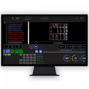
Manufacturing software also provides operational information beyond the initial design stage. Production timestamps, operation counts, and machine running records help factory managers evaluate manufacturing activities against planned schedules. These records support more informed production decisions while maintaining a clearer connection between approved project documentation and completed manufacturing operations.
Cold-formed steel offers a versatile approach to modern construction, combining structural efficiency with adaptable design and manufacturing methods. Achieving successful project outcomes requires careful coordination between engineering, production, and installation. Arkitech supports this process through integrated Light Gauge Steel (LGS) framing machines, advanced design and manufacturing software, and engineering solutions. Explore Arkitech’s LGS solutions to discover how its technology can support your construction projects and manufacturing requirements.
FAQ
What is cold formed steel framing?
Cold-Formed Steel (CFS) framing is a construction method that uses lightweight steel profiles to create structural and nonstructural building assemblies. It provides dimensional accuracy and supports prefabrication, making it suitable for projects requiring consistent manufacturing quality.
What are cold formed steel sections and profiles?
Cold-formed steel sections and profiles are manufactured from steel sheets formed into specific cross-sectional shapes. Common configurations include C-Section and U-Section profiles. Their dimensions, thicknesses, and geometry are selected according to their intended structural functions.
How is cold formed steel used in construction?
Cold-formed steel is used in residential, commercial, industrial, and modular construction. Applications range from prefabricated building components to internal partitions and extensions. Its versatility allows engineers to develop solutions for different architectural layouts and project requirements.
What is structural cold formed steel?
Structural cold-formed steel consists of engineered steel members designed to resist and transfer building loads. Unlike nonstructural framing, these components must satisfy specific strength, stability, and serviceability requirements under applicable structural design standards.
Can cold formed steel be used for wall and roof framing?
Yes. Cold-formed steel can be used for both wall and roof framing, including complex architectural designs. Its suitability depends on span requirements, environmental loads, structural calculations, and the specified connections between individual framing components.
What does a cold formed steel framing machine do?
A cold-formed steel framing machine transforms steel coils into precisely dimensioned construction profiles through automated roll forming. Depending on its configuration, it performs punching, cutting, notching, and marking operations using digital manufacturing data.

 by